
Arduino Clock Atmega1284p with MIDI player and Hobby
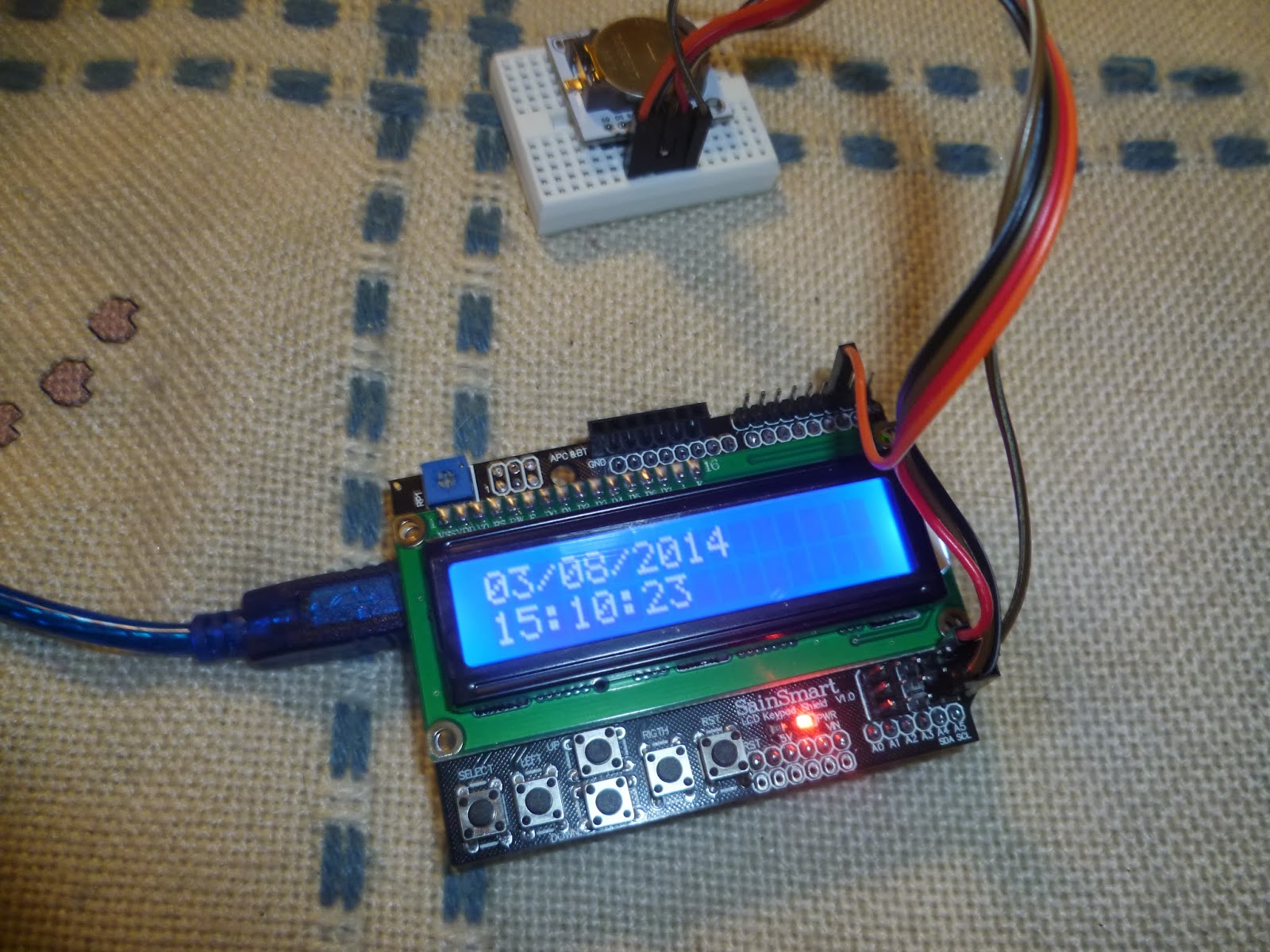
The design of the Arduino RTC Interface is quite straight forward. Connect the SDA and SCL pins of the DS1307 RTC to the SDA and SCL pins of Arduino i.e. pins A4 and A5. A 16×2 LCD is connected in order to display the data and time information. The connections are made as per the circuit diagram.

Arduino Clock With a Dc Motor (single Needle) 4 Steps (with Pictures
Building a clock with Arduino is easier than you think. All you need to get started is an Arduino prototyping board and some type of display, preferably one with at least eight characters. I will be using an Arduino Uno board with a Sparkfun 16×2 LCD display. To set the time on the Arduino, we will be sending a Unix Timestamp over serial using.
arduino dht22 wiring
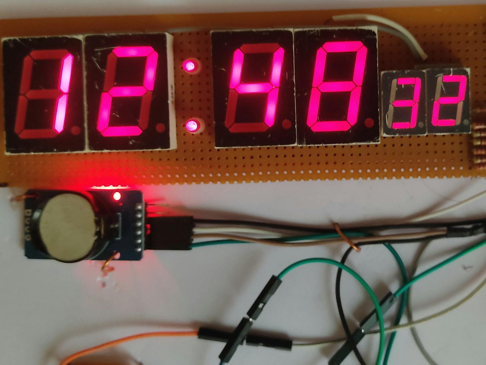
In this tutorial, we are going to learn how to make 7-segment clock using Arduino. In detail, we will learn two cases: Arduino reads time ( minute and second) from DS3231 RTC module and display it on the TM1637 4-digit 7-segment module Arduino reads time ( hour and minute) from DS3231 RTC module and display it on the TM1637 4-digit 7-segment module

Arduino Clock With DS3231 and LCD1602 3 Steps Instructables
1 Arduino UNO 1 Standard LCD - 16x2 White on Blue Project description I tried the clock from here: https://www.hackster.io/Annlee_Fores/simple-arduino-digital-clock-without-rtc-7d4303 and found lots of problems in it, so decided to improve it. Now the incrementation of s will be every 1 second and no more depending from the loop {} execution time.

Randstein Veraltet Ort arduino uhr ohne rtc Haltung Berechnung Hohl
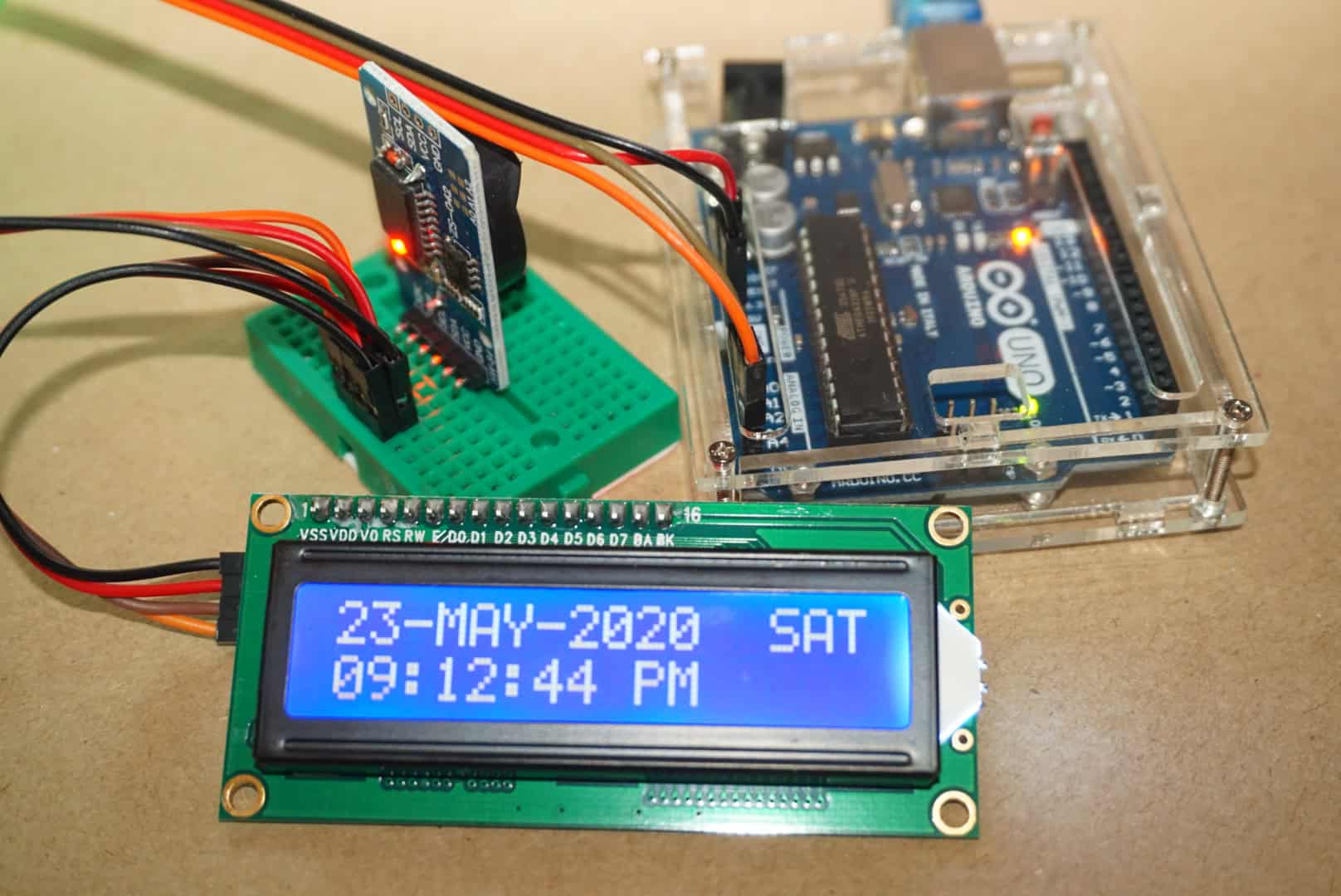
In this tutorial, we are going to learn how to make LCD clock by: Reading date and time from DS3231 RTC module and display it on an LCD I2C 16x2 Reading date and time from DS1307 RTC module and display it on an LCD I2C 16x2 You can choose one of two RTC modules: DS3231 and DS1307. See DS3231 vs DS1307 Hardware Required

Talking Clock With Arduino 3 Steps (with Pictures) Instructables
Circuit Diagram Connect the LCD to the Arduino as follows: Pin 1 on the LCD to ground on the Arduino. Pin 2 on the LCD to 5V on the Arduino. Pin 3 on the LCD to the middle pin on the 10K potentiometer. Pin 4 on the LCD to digital pin 2 on the Arduino. Pin 5 on the LCD to the ground of Arduino. This will put the LCD in read mode.

Electronic projects Arduino LED clock
Set the current time in the Real Time Clock. For setting the current time you need to change the code provided. set your current time int the function setDS3231time () The parameters for the function are highlighted in red: seconds, minutes, hours, day of the week, date, month and year (in this order). Sunday is the day 1 of the week and.
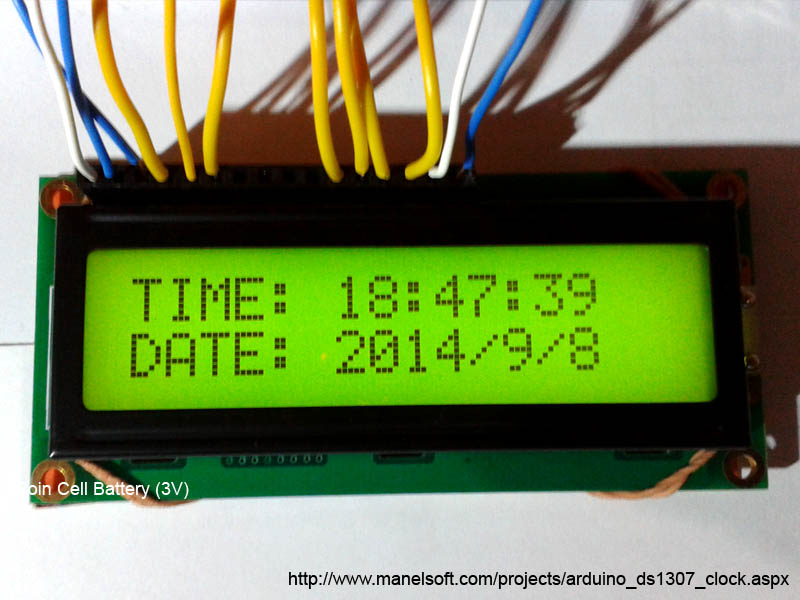
Arduino DS1307 Clock
The most common clock models are the DS1302, DS1307, DS3231. They have based on an RTC (real-time clock) module connected to the Arduino. It can generate seconds, minutes, hours, day, date, month and year and provide time until 2100, and with leap year compensation. Working voltage: 3.3 -. 5 .5 V.
How to Use a Realtime Clock Module with the Arduino Circuit Basics
Building a Smart RGB Clock with Arduino In today's digital age, clocks have gone beyond mere timekeepers; they have become statement pieces that blend functionality with artistry. In this.

Arduino Timer With On/Off Set Point 6 Steps (with Pictures
1 /* Demonstration of Rtc_Pcf8563 Set Time. 2 * Set the clock to a time then loop over reading time and 3 * output the time and date to the serial console. 4 * 5 * I used a RBBB with Arduino IDE, the pins are mapped a 6 * bit differently.

Arduino alarm clock project
Step 1: Requirements The following things are required to get this project done: 1- Arduino Mega or Arduino UNO 2- Potentiometer (eg 5K) 3- LCD 16x2 4- Two Push Buttons Step 2: Pin-outs & Wiring The Pin-outs & Wiring of Arduino Mega or Arduino UNO and other peripheral is attached with this step and also given following: ============= Arduino => LCD
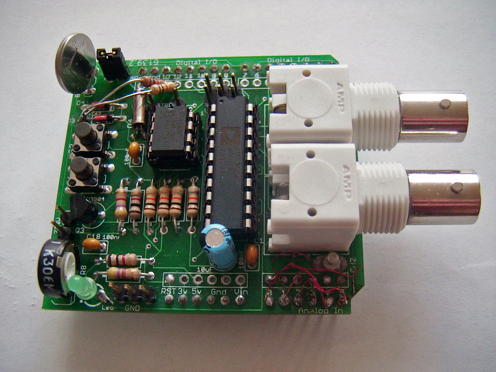
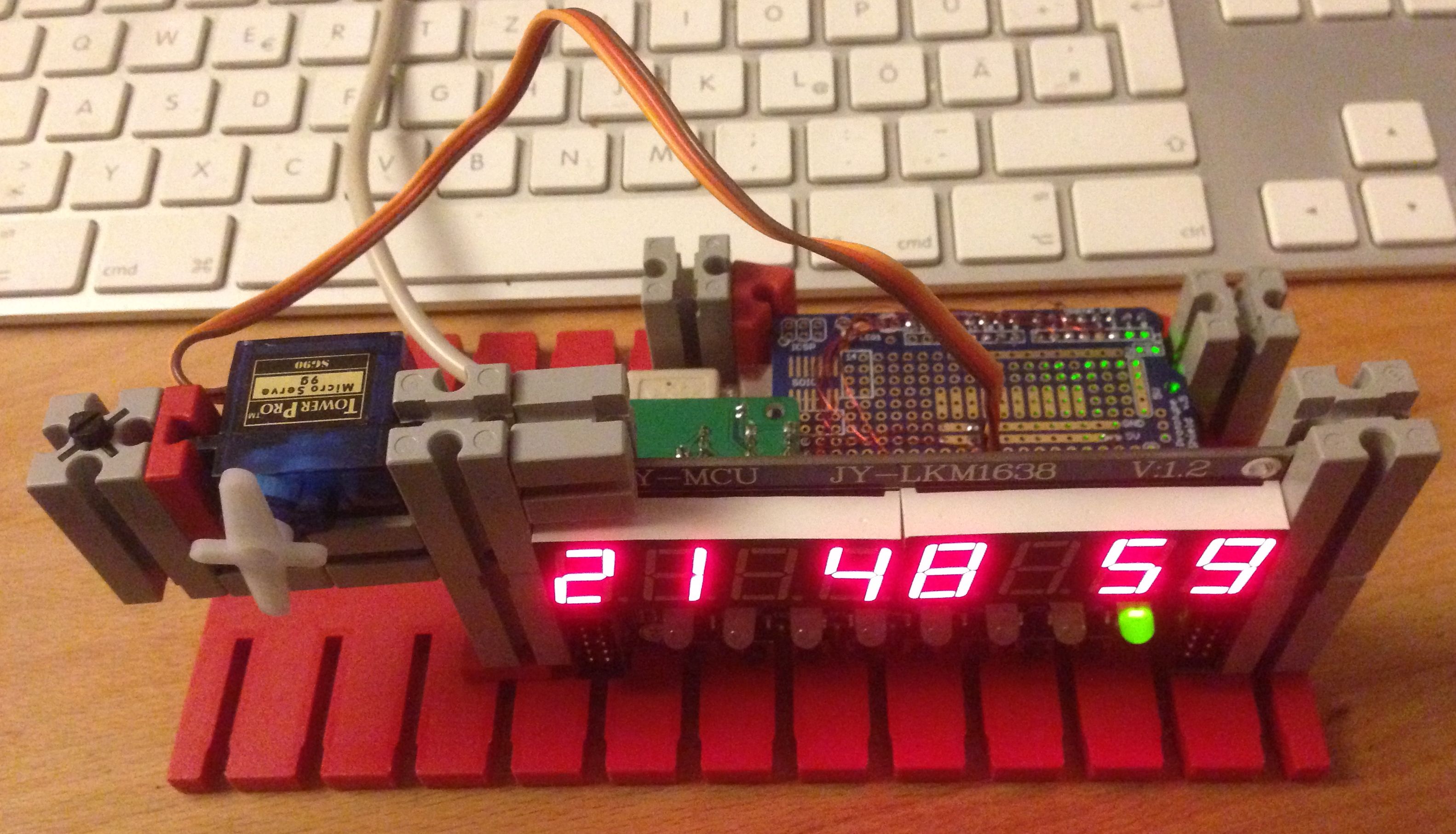
Arduino ClockShield
1 // Paul Brace Feb 2021 2 // Script to accept millis() from Arduino 3 // 4 and compare it to internal millis to 5 // assess inaccuracy of the Arduino clock. 6 // 7 Assumes that the computer clock is accurate 8 // -ve = Arduino is running slow 9 so enter as a + ve adjustment in the clock program 10 // +ve = Arduino is running 11 fast so enter.

Simplest Arduino Clock With 7digit segment display Slawomir Jasinski
Step 1: Components Required Here the Components that you will Require : 1. An Arduino uno. 2. 4 7 segment common anode displays (if you have a 4 digit seven segment , don't worry the circuitry is same for both of them). you can buy them from snapdeal , they are great ! i would recommend them from the site.
Digital Clock using Arduino Nano Hackster.io
Step 1: Parts For this Instructable, you will need: 1 Arduino (I used an Arduino-nano) 1 LTC-617 clock display (you might need to solder male headers onto it) many jumper wires 1 button 1 resistor: 10k or close (to prevent short between gnd and 5v on button press) For me this was a no-cost project as I already had all the parts.

Electronic projects Arduino LED clock
Setting up time in the DS3231 module is fairly simple. All you need to do is connect it to the Arduino in the below configuration. After making the above connections, you need to connect the Arduino UNO to your PC, open Arduino IDE, and install Arduino DS3231 Time Set Library. Open the Arduino IDE and select Library Manager from the menu bar.
Easy Arduino LED Clock Johannes' Blog
Step 1: Gathering Materials While there is a lot of materials used for this project, most of them are fairly inexpensive. The list of materials I used follows below: Materials: 2' x 3' Sheet of 5/8" Plywood 2 feet of 2" OD ABS Pipe 3 feet of 1" OD PVC Pipe 3 feet of 3/4" OD PVC Pipe